|
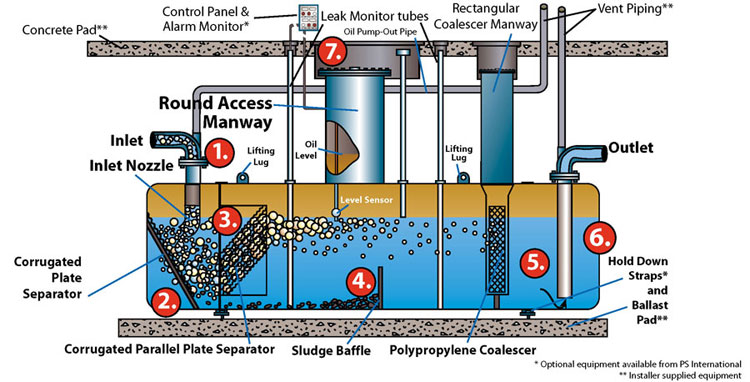
 Inlet and outlet piping enters the vessel through the top centerline of the separator per UL-58 requirements. This assures that the separator always operates full of liquid, thus utilizing the total volume of the vessel. Inlet and outlet piping enters the vessel through the top centerline of the separator per UL-58 requirements. This assures that the separator always operates full of liquid, thus utilizing the total volume of the vessel.
 Flow is directed towards a single corrugated plate at an angle perpendicular to the entrance pipe. This method of separation, known as the Buffalo- Morse Principle, serves multiple functions: Flow is directed towards a single corrugated plate at an angle perpendicular to the entrance pipe. This method of separation, known as the Buffalo- Morse Principle, serves multiple functions:
- It reduces the velocity head of the incoming stream.
- It spreads the flow out over the entire cross sectional area of the separator and prevents channeling of the flow.
- The plate corrugations create sinusoidal flow patterns, which cause solids to break out of the flow stream and oil droplets to collide and coalesce.
 The second stage of separation in the PSI separator is based upon the proven Royal Dutch Shell Principle of using multiple corrugated parallel plates. The parallel plate pack in the PSI oil-water separator consists of a special arrangement of heavy gauge removable corrugated steel plates. The second stage of separation in the PSI separator is based upon the proven Royal Dutch Shell Principle of using multiple corrugated parallel plates. The parallel plate pack in the PSI oil-water separator consists of a special arrangement of heavy gauge removable corrugated steel plates.
|
The plates are inclined at a 45 degree angle to prevent the accumulation of solids and the plate spacing is large enough to prevent plugging from debris and trash. An open area is located directly below the plate frame to prevent the accumulation of solids in front of the plate pack. The plate pack provides a crucial role in separation so it is vital that this pack is located in the front end of the vessel in order to maximize the effective separation chamber of the separator. This is the case in the PSI design.
 The internal sludge baffle in the PSI separator serves two primary functions. First, solids are carried downstream in the separator by the internal hydraulics of the vessel where they collect in front of the sludge baffle. The baffle is located directly below the access manway for easy sludge removal from grade. Second, the sludge baffle directs the flow from the bottom quadrant of the separator towards the top of the vessel aiding in the floatation of small oil particles in the flow stream. The internal sludge baffle in the PSI separator serves two primary functions. First, solids are carried downstream in the separator by the internal hydraulics of the vessel where they collect in front of the sludge baffle. The baffle is located directly below the access manway for easy sludge removal from grade. Second, the sludge baffle directs the flow from the bottom quadrant of the separator towards the top of the vessel aiding in the floatation of small oil particles in the flow stream.
 PSI can provide, as an option, an additional polypropylene coalescer. This consists of a special matrix of polypropylene fibers designed to coalesce oil droplets down to 20 microns in size. An important addition to the PSI separator design is the use of a large coalescer access manway that spans the entire cross section of the coalescer and includes dedicated tracks for the coalescer. PSI can provide, as an option, an additional polypropylene coalescer. This consists of a special matrix of polypropylene fibers designed to coalesce oil droplets down to 20 microns in size. An important addition to the PSI separator design is the use of a large coalescer access manway that spans the entire cross section of the coalescer and includes dedicated tracks for the coalescer.
|
This ensures easy removal and reinstallation of the coalescer from grade. Other separators require maintenance personnel to “fish” their polypropylene coalescer out in pieces through a small access manway. These designs make it difficult if not impossible to reinstall the coalescers without draining and entering the vessel.
 The outlet pipe is located at the end of the separator and draws clean water from the most quiescent section of the vessel. The effluent will contain a free oil and grease discharge of no more than 15 ppm in PS and PSR model separators and no more than 10 ppm in PSC and PSRC model separators. The outlet pipe is located at the end of the separator and draws clean water from the most quiescent section of the vessel. The effluent will contain a free oil and grease discharge of no more than 15 ppm in PS and PSR model separators and no more than 10 ppm in PSC and PSRC model separators.
 PSI has the experience to provide solid state control systems to meet a wide variety of fluid level monitoring and flow control requirements including intrinsically safe liquid level sensors and custom-built control panels. Installing a high performance PSI separator to meet your discharge requirements along with a maintenance warning system will alleviate your wastewater treatment worries. PSI has the experience to provide solid state control systems to meet a wide variety of fluid level monitoring and flow control requirements including intrinsically safe liquid level sensors and custom-built control panels. Installing a high performance PSI separator to meet your discharge requirements along with a maintenance warning system will alleviate your wastewater treatment worries.
|

